

Since the FTDI driver version 2.06.00 is Microsoft WHQL certified the installation
becomes very simple. Just download and
run driver executable once. Driver is also available here (FTDICHIP website).
Manual for installation under Windows 7 is available here.
Firmware downloading is not supported yet trough the software in PC. It is necessary send FITPix to the IEAP if is need of new firmware.
If you have a programmer from Lattice (
HW-USBN-2A
), there is another option for firmware upgrade.
Procedure of upgrade:
1. Download ispVM System and install.
2. Join programmer and install drivers (drivers are in the folder system of ipsVM System). Run ipsVM System.
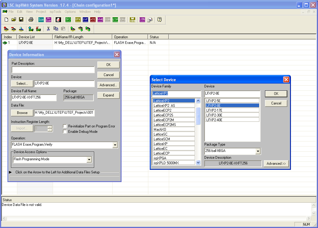
3. Use Add Device button.
4. Use Select... button and choose LatticeXP2 -> LFXP2-8E -> 256-ball ftBGA.
5. Choose the firmware file with Browse button.
6. Operation must be FLASH Erase,Program,Verify and Device Access Options must be Flash Programing Mode. Press OK.
7. Use button Download (green GO or CTRL+G).
Last version of firmware will be send after request.
Last version of firmware Firmware 2 (date: 24. 1. 2011).
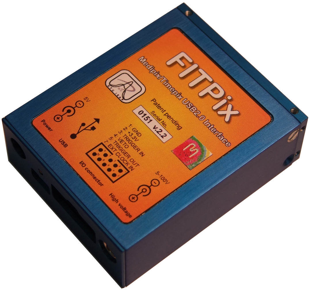
FITPix interface is fully supported in Pixelman. Java version of Pixelman is recommended. Pixelman is available here.
![]()
After start the software automatically find connected FITPix interfaces and
recognize amount of Timepix chips (single, quad) - if connected. Control of Pixelman is like with older interface.
The picture below shows list of modes for measurement. Burst activates high frame rate (up to 80 fps). There is 50 fps without burst mode.

Description of measurement:
HW Timer: The time of measurement is determined by the HW timer. Value of HW timer sets Acq. time in Pixelman.
Started by HW trigger, stopped by timer: Measurement is started by falling edge on the signal External trigger. The time period is determined by the HW timer.
Started immediately, stopped by HW trigger: Measurement starts immediately in this trigger mode and FITPix is waiting for event on the signal External trigger. Falling edge terminates measurement. The information about time period is available.
Started by HW trigger, stopped by HW trigger: Falling edge starts and terminates measurement. The information about time period is available.
The picture below shows new items in Interface specific info.
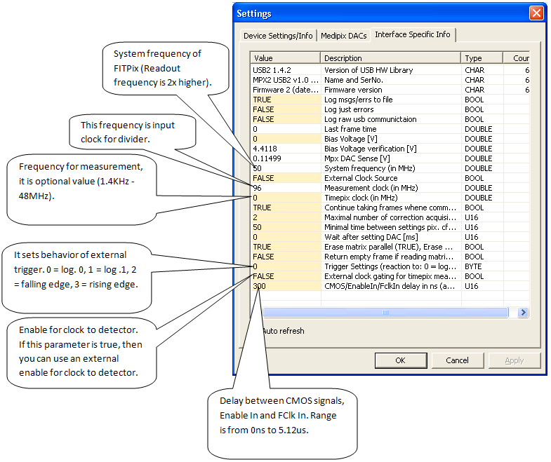
System frequency: . FITPix uses 50 MHz. This main system clock can be different with version of firmware. Pixelman obtains value of system clock after start of FITPix.
ClkIN: FITPix uses 96 MHz. This clock is input for clock divider and output from clock divider is used for measurement. Clock divider is 16 bits counter.
The range is from 1.4 kHz to 48 MHz. This clock can be different with version of firmware. Pixelman obtains value of this clock after start of FITPix.
Timepix clock: This clock is the output from clock divider and this clock is used for measurement. It feeds FCLK_IN.
1. HW Timer: The time of measurement is determined by the HW timer. Value of HW timer sets Acq. time in Pixelman.

2. Started by HW trigger, stopped by timer: Measurement is started by falling edge on the signal External trigger. The time period is determined by the HW timer.
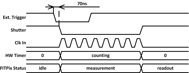
3. Started immediately, stopped by HW trigger: Measurement starts immediately in this trigger mode and FITPix is waiting for event on the signal External trigger. Falling edge terminates measurement. The information about time period is available.

4. Started by HW trigger, stopped by HW trigger: Falling edge starts and terminates measurement. The information about time period is available.

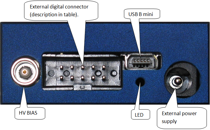
| PIN | SIGNAL | DIRECTION | LOGIC | Description |
| 1. | GND | Power | - | - |
| 2. | +5V | Power | - | - |
| 3. | Trigger_In | IN | 3.3V CMOS (5V Tolerant) | Falling edge starts measurement if triggering measurement is enabled. |
| 4. | Veto | IN | 3.3V CMOS (5V Tolerant) | Logic low causes erase of matrix and then FITPix system is waiting for next command. |
| 5. | Trigger_Out | OUT | 3.3V CMOS | If measurement (Shutter = log. ) is active this signal is in log. 0. |
| 6. | Trigger_Busy | OUT | 3.3V CMOS | If this signal is log. 1 then FITPix interface is not capable to perform external event. |
| 7. | Ext_Clock_In | IN | 3.3V CMOS | This input is dedicated for custom clock signal for detector. It is necessary to set up this settings in Pixelman. |
| 8. | Clk Enable | IN | 3.3V CMOS | Clock gating for Timepix. Log. 0 = Clock for detector is disabled. Log. 1 = Clock for detector is enabled. This feature must be enabled in the Interface Specific Info |
| 9. | GPIO(0) | IN/OUT | 3.3V CMOS | General Purpose. |
| 10. | GPIO(1) | IN/OUT | 3.3V CMOS | General Purpose. |