
Medipix2 and Medipix3 are collaborations between number of European Universities and Research Institutes. The aim of the Collaboration is to carry out the design and evalutation of the semiconductor pixel detectors called Medipix (or newly Timepix). The hybrid silicon pixel detector device Medipix was designed for imaging by single quantum counting in each pixel. The device consists of a pixelated sensor chip and a read-out chip containing the amplifier, discriminators and counter(s) for each pixel.
Medipix - counting
 Medipix - counting
Medipix - data read-out
The serial readout uses a LVDS port to shift out all the matrix data. In readout mode the 14-bit shift register of each pixel is connected to the next one forming a 3584-bit shift register. Communication between the pixel matrix and the IO logic is carried out through the 256-bit FSR. The number of clocks needed in order to read one chip are 917512 (256x256x14+8). External clock have to be used to shift the data from pixel to pixel.
 Medipix - data read-out
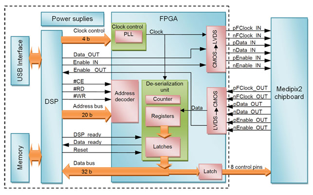
 RUIN - Block diagram
 Data de-serialization
New interface design puts emphasis on:
Strategy :
Conecting with PC
Usage of the digital signal processor
Usage of the FPGA
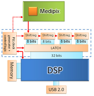
Principle of data de-serialization:
Serial data from Medipix are not loaded directly to the signal processor but are first de-serialized
Individual chips of the multichip assembly (Medipix Quad) can be read out simultaneously (the 32-bit fast shift register can be divided into four parallel 8-bit segments). Each segment can be fed from a separate Medipix chip.
 RUIN - Block diagram
To be more flexible we decided to use modular system
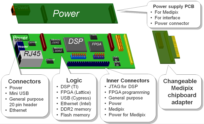 PCB Layout
All signals from Medipix go via the FPGA (Lattice XP) with configurable inputs outputs – LVDS, CMOS
Changeable chipboard adapter is recognized automatically and LVDS and CMOS pins of FPGA are configured.
Supported Detectors
Detectors:
Read-out:
Connecting:
Dimensions
Data read-out and control
Current prototype fully tested with MXR chip (up to 48 MHz)
Schematic design is finished
PCB is ordered.
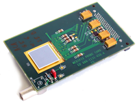
 RUIN prototype
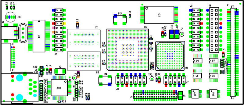 PCB design