Pixelman - Manual
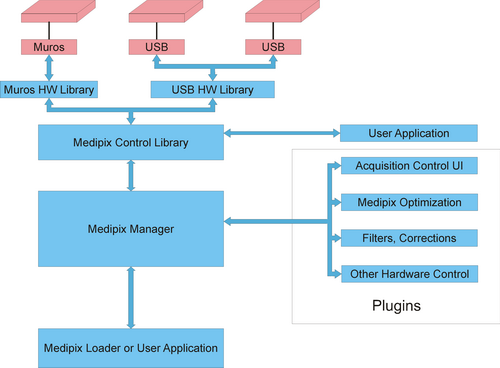
Pixelman has an open and flexible modular architecture
with custom-made plugin support enhancing its functionality to fit experiment needs.
The core of Pixelman is composed of several parts - Medipix Manager,
Medipix Control library and Hardware Libraries.
Hardware libraries provides access
to connected Medipix2. One hardware library corresponds to each interface type -
MUROS, USB, Dummy. Dummy hw library simulates connected Medipix2 and is present
mainly for developers. Medipix Control library manages all connected
Medipix2 devices, their settings, configuration files, buffers for data, and
provides access to them for Medipix Manager. Medipix Manager
manages communication between all parts - initialize plugins, handle functions
registered by plugins, provides access to Control library for plugins,
handles events and much more. All other functionalities including most of user
interface are implemented as plugins. The architecture can be seen in following
figure.
Pixelman directory structure
Pixelman main directory contains core files - MpxCtrl.dll,
MpxManager.dll, MpxMgrUtils.dll and MpxLoader.exe. Only these files
are really required to run Pixelman. Other files that might be present are:
- MpxManger.ini - ASCII ini file that contains e.g. path to plugins
that should be loaded on startup. If you want remove some plugin just delete
corresponding line,
- log.txt - ASCII file with system messages and errors,
- __debug_muroshwlib.log - trace file for MUROS hw library,
- __debug_USBhwlib.log - trace file for USB hw library.
Configs directory contains default configuration files for
individual Medipix devices and cofig. files for plugins. The files with extension
mcf (mcf stands for "medipix configuration file",
ASCII file) contain settings like polarity, Medipix2 DACs values etc. The
files with extension bpc ("binary pixels configuration")
contain default pixel configuration (mask bit, test bit, THL bits, THH bits,
binary file - one byte for each pixel). These files hold last configuration of
each device - this configuration is loaded when Pixelman is loaded and are
replaced by current configuration during Pixelman exit. The name of configuration
file is derived in the following way: if chip is Medipix2 MXR (which contains
unique "wafer position" identification) the name is
interfacename_uniqueid, if chip is non-MXR and interface is USB
(which contains serial number) the name is USB_serialnumber. If chip
is non-MXR and interface is MUROS the name is muros_1001, muros_10002, etc.
Hwlibs directory contains HW libraries and configurations
files for individual interfaces (currently MUROS, USB, Dummy). dummy_2000.txt
contains reference picture used as output of dummy devices. Number of dummy devices
can be specified in mpxHwDummy.ini. If you want different output from
different dummy devices add dummy_2001.txt, dummy_2002.txt, etc. and
set Unique=1 in mpxHwDummy.ini.
Plugins is a default directory for plugins (they can be placed
in any directory, this is just preferred location).
Starting Pixelman
Run Medipix Loader (MpxLoader.exe) to start. Loader is just simple
application which loads and initialize Medipix Manager. The rest of initialization
is done by Medipix Manager. During initialization Pixelman creates tray icon which
will appear on the task bar. Right click on the icon to open tray menu. For each
detected device there will be submenu with name derived in the following way: if
chip is Medipix2 MXR (which contains unique "wafer position" identification)
the name is devID - interfacename uniqueid (e.g. "1 - muros I10 -
W13"), if chip is non-MXR and interface is USB (which contains serial number)
the name is devID - usb serialnumber. If chip is non-MXR and interface is
MUROS the name is devID - muros 1001, devID muros 10002,
etc. "devID" is Pixelman internal number assigned to detected device
(starting from 0, and increasing for each detected device). The submenu contains
menu items which were created by registered plugins and are unique for each detected
device. Each item usually opens user interface for corresponding plugins (e.g.
Medipix Control opens window of MpxCtrlUI.dll plugin, Threshold
equalization opens dialog for equalization etc.). Plugins in these sub menus
are so called "per-device plugins" which opens window which controls
single Medipix device. So for each detected device you have one window (or set
of windows). Example of such plugin is DAC control panel. You can have this panel
open for each detected device. The second group of plugins are so called "global
plugins" which are not bound to single device. They can control all plugins
simultaneously or not use Medipix devices at all. So these plugins have only one
set of user interface totally (and not one set per device). Example of such plugins
are e.g. Coincidence plugin (which controls several devices at time) or
Frame Browser plugin (which does not access Medipix at all).
These "global" plugins are currently contained in "Utilities"
submenu.
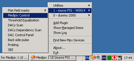
Other items in tray menu are:
- Add Plugin menu item opens file browser dialog so you can
find new plugin which you want to add to Pixelman.
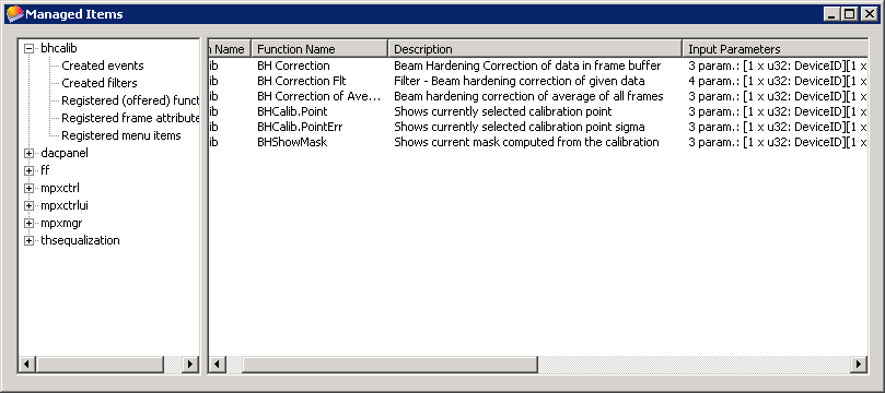
- Show Managed Items opens window where you can see which
items are currently managed by manager (like registered functions, events,
filters,...).
- Show Log opens window with logged messages.
- Find New Mpx Devices tries to find new connected devices.
- About shows about dialog.
- Exit shutdowns Pixelman.
Managed items window:
Medipix Control UI
Medipix Control UI is plugin which provides simple interface for acquisition control.
There are several windows - main window, preview window and
settings sheet.
Main window
Acquisition can be started by clicking Start button (or through menu
Acquisition->Start). If acquisition is running it can be aborting by
clicking the same button which is changed during acquisition to Abort
(Acquisition->Abort). If any error occurs it will be shown in Info
and error messages list box. The following options are available:
- Acq. type - the type of acquisition (Frames, Integral, Test pulses). If "Frames" type is selected each frames is stored in 2byte per pixel counter. In "Integral" mode all measured frames are integrated to one buffer 4bytes per pixel.
- To files - if checked measured frames are not held in memory but are written to files. "Base" path and file name can be set in edit box or browsed via "..." button. If "Frames" acq. type is selected the file name consist from "base" name and acq. index - e.g. if base name is set as "c:\data\frame.txt" and 50 "Acq. count" is set to 50 frames the names for files will be "c:\data\frame00.txt", "c:\data\frame01.txt", ..., "c:\data\frame49.txt". If "Binary format" is checked the files are written in binary format (2 bytes integer per pixel in "Frames mode", 4 bytes in "Integral" mode). If binary is unchecked the files are written as ASCII matrix.
- Acq. count - number of acquisition that should be measured
- Acq. time - time of each acq. in seconds
- Spacing - influence how many pixels is active during single acquisition. Useful mainly for test pulse acq. If spacing is 1 all pixels are active (acquisition has just 1 "subacquisition), if spacing is 2 every second pixel in each direction is active (acquisition has 4 subacquisition), if spacing is 3 every third pixel in each direction is active (there is 9 subacquisition).
- Repeat - if checked whole acquisition series will repeat selected number of times. If repeat count is set to 0 it will repeat indefinitely until "Repeat" is unchecked or "Abort" is pressed. "Delay" defines time delay interval in seconds between acq. series. If you uncheck "Repeat" during acq. the currently running series is finished. If you press "Abort" acq. process is immediately aborted. If output to files is enabled and repetition is active there will be an repetition index in filename - e.g. if base name is "c:\temp\data.txt", acq. count=5, repetition count=3 the file names will be: "c:\temp\data_r0_0.txt", "c:\temp\data_r0_1.txt", ...,"c:\temp\data_r0_4.txt", "c:\temp\data_r1_0.txt",..., "c:\temp\data_r2_4.txt"

The structure of File menu:
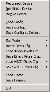
- Reconnect Device - if you change Medipix device on this interface you can force auto detection and initialization of this new device
- Reinitialize Device - performs the same initialization of current device as if Pixelman was started, the last saved config is loaded (the same config as Pixelman was started)
- Revive Device - it just reinitializes the device but current configurations (DACs, pixels cfg.,...) is preserved and again send to chip. It just reinitialize device e.g. if USB interface was disconnected or connection was lost.
- Load Config - load medipix configuration file (*.mcf)
- Save Config - save current configuration (DACs, polarity, timer,...) to specified *.mcf file
- Save Config as Default - save current configuration (DACs, polarity, timer,...) as default configuration. That means that this setting will be set if new device is connected.
- Set Mode - sets Timepix mode for whole matrix (Timepix chip only)
- Medipix
- Time over Threshold
- Timepix 1-hit
- Timepix
- Reset Pixels Cfg
- All Bits - sets all cfg. bits to default values (unmasked, test bit off, THL/THH adj bits off = 7), if chip is Timepix the mode is set to Medipix mode
- Mask Bits - unmask whole matrix
- Test Bits - disable test bit for whole matrix
- THL Ajd. Bits - sets THL adj. bits to 7
- THH Adj. Bits - sets THH adj. bits tai 7 (unavailable for Timepix)
- Load Binary Pixels Cfg - load pixel configurations from binary file (*.bpc)
- Save Binary Pixels Cfg - save current pixel cfg. to selected binary file
- Load ASCII Pixels Cfg
- Load Mask Bits - load mask bits from ASCII file
- Load Test Bits - load test bits from ASCII file
- Load Low Thresholds - load THL adj. bits from ASCII file
- Load High Thresholds - load THH adj. bits from ASCII file (unavailable for Timepix)
- Lode Mode Mask - load Timepix mode mask from ASCII file (Timepix only)
- Save ASCII Pixels Cfg
- Save Mask Bits - save current mask bits values to ASCII file
- Save Test Bits - save current test bits values to ASCII file
- Save Low Thresholds - save current THL adj. bits values to ASCII file
- Save High Thresholds - save current THH adj. bits values to ASCII file (unavailable for Timepix)
- Save Mode Mask - save Timepix mode mask from ASCII file (Timepix only)
- Load Frame - load frame to Pixelman (much more options in Frame Browser plugin)
- Save Frames - saves frames from last series of acquisition to files (ASCII or binary format can be selected in save dialog)
- Exit - quits Medipix Control plugin
The structure of Acquisition menu:
- Start - start acq.
- Abort - aborts running series acq.
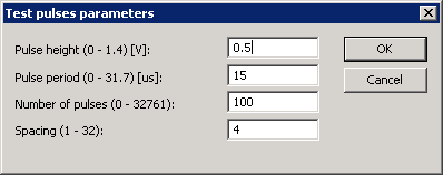
- Test Pulses Parameters - invokes dialog for setting Test pulses parameters
The structure of Options menu:
- Device Settings... - open modal setting sheet
- Preview Visible - if checked preview window is opened
- Autostart - if checked this plugin (Medipix Control UI) will be automatically started for this Medipix device
- Refresh DACs - if checked the DACs values are sent to chip after clicking Start (that means DACs values are "refreshed" before each series of acquisition)
- Refresh Pixels Cfg - if checked pixel configurations (mask bits mask, test bits mask, THL/THH adjustment bits masks, mode bits for Timepix) are sent to chip after clicking Start button.
- Load/Save DACs with Pix. Cfg. - if checked and you save pix. cfg. to file also file with DACs is created (which has the same name with extension .dacs). If you load pix. cfg. and this option is checked Pixelman tries also corresponding DACs file.
Settings sheet
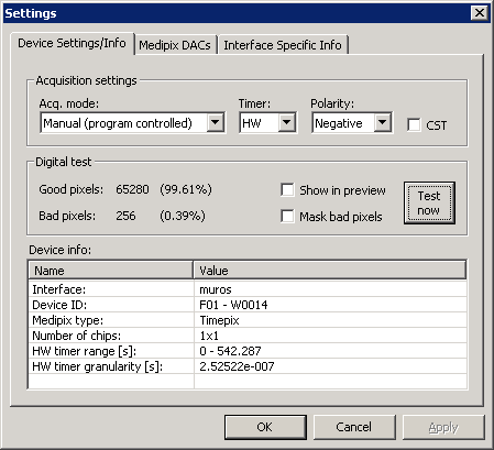
Settings sheet is invoked by Options->Device Settings:
Device Settings/Info page
Acquisition settings:
- Acq. Mode - selection acq. modes which are supported by interface/HW library.
- Timer - HW (shutter time is controlled by interface), PC (shutter time is controlled by PC), Auto (settings depends on acq. time - if the time fits HW timer range HW timer is used, otherwise PC timer).
- Polarity - polarity settings - Positive (hole collection), Negative (electrons collection)
- CST - enables/disables Charge Sharing Test
Digital Test:
After clicking "Test now" button digital test is
performed. That means that random matrix is written to chip a read back, if
values are different for some pixels it means its digital part does not work
correctly. If "Show in preview" is checked the result
of test is displayed as a frame in Preview window (bad pixels have value of 1,
good 0). If "Mask bad pixels" is checked the pixels
which fails digital test are masked.
Device info part contains basic information about device
like Medipix type, Mpx ID, interface name, number of chips, parameters of HW timer.
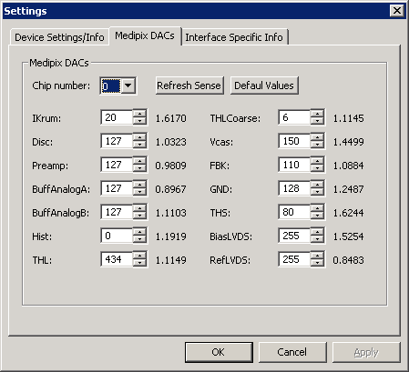
Medipix DACs page
DACs page allows to control Medipix DACs and shows corresponding analog values.
This page is generated dynamically according to detected Medipix type. If you have
quad you can select chip number in Chip number combo box. If one
clicks Refresh Sense button the analog values are read again. If
you change DACs value click Apply button to send new DACs values
to Medipix and to automatically refresh analog values. If you change DACs values
and click OK button the values will be send to chip and settings
dialog will be closed. After clicking Default Values button the
default values will be set.
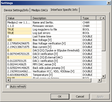
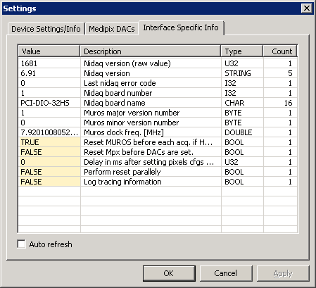
Interface Specific Info page
Interface Specific Info page shows informations which are relevant only for current
type of interface. These informations are received from hw libraries as a list
of "unknown" items which are fed to list box. The highlighted items are
editable and can be used for controlling certain interface-specific settings. You
can edit by clicking on item (to have focus on item) a then click second time to
edit item. If item is boolean type you can write "TRUE", "true"
or just "1" for true settings (similarly for false). If Auto
refresh is checked the items are read-back from hw library in regular
intervals (useful e.g. for bias monitor in USB interface).
Interface Specific Info for MUROS shows informations Nidaq version
installed, type of NI board, Muros clock frequency. The editable items are:
- Reset MUROS before... - this settings is because of problem with stability if MUROS timer. The MUROS timer works correctly just after MUROS reset. So there is workaround which reset MUROS before each acquisition. In original MUROS firmware the reset of MUROS caused reset of Medipix chip. There is an updated version of MUROS firmware which during MUROS reset does not perform reset of Medipix. If you have correct firmware and you use MUROS HW timer you should have this item set to TRUE.
- Reset Mpx before... - Workaround for problem with threshold that appears with MXR chips if chip is equalized and is in deep noise (should be TRUE for MXR).
- Delay in ms... - with original 2.1 chip (non-MXR) there was observed a problem that if pixel configurations (masks) are set it take some time before thresholds are stabilized. So here is an optional delay (in ms). 100ms is default value. For MXR chips there is no need to wait and this value should be set to 0.
- Perform reset parallely - enables parallel reset
- Log tracing information - if TRUE detailed information are written to __debug_muroshwlib.log trace file. It should be enabled only if you have some problems with device connected via MUROS and you want to send us trace file which can help us to trace problem.
Interface Specific Info for USB displays a lot of informations
about current settings which are not particularly interesting for common user.
Here is few basic option:
- Bias Voltage - bias applied to detector, range is 40 - 104 V, set 0 to off
- Log msgs/errs to file - enable/disable tracing in hw library
- Log just errors - only errors are logged
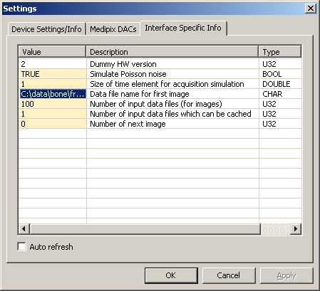
Interface Specific Info for Dummy. Editable items:
- Size of time element... - amount of time (in s) which corresponds to predefined image. If time element is 2 s and acquisition time is 6 s the frame which will be returned by dummy hwlib will be 3*reference image + corresponding Poisson noise (if selected)
- Data file name for... - Dummy device can be set to use a set of input files (which can be e.g. saved data from real Medipix) for its output. To do that set this item to file path to first image that should be used as an output sequence.
- Number of input data... - number of files that should be used from sequence. E.g. if you have saved data from measurement and you want to use frames from files "c:\data\frame020.txt", "c:\data\frame021.txt", ..., "c:\data\frame120.txt", you set the first file ("c:\data\frame020.txt") to Data file name for first image and as number of input files you specify 101 (indexes 20-120).
- Number of ... cached - number of files that could be cached (i.e. should be held in memory). If Number of input data... will be less than this number files will be held in memory. Otherwise they will be read from file each time they are required.
- Number of next image - index of image that will be used in next acq. So if you e.g. want to start sequence from start set this value to 0.
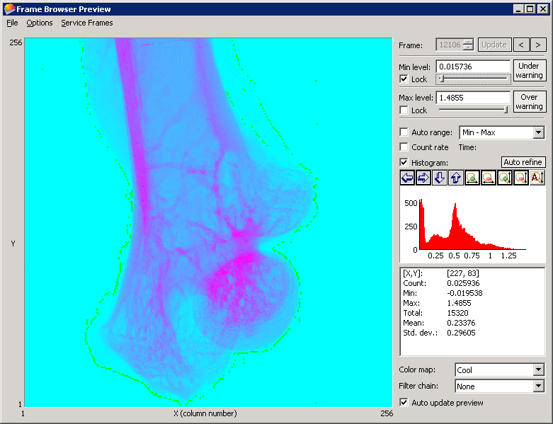
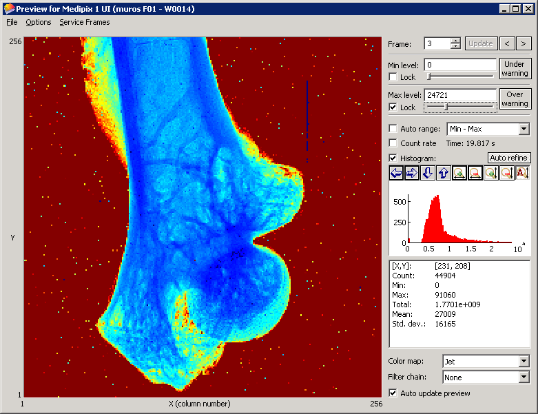
Preview window
The visibility of preview window can be set in Options menu.
This preview can be used to watch the progress of current serie of acquisitions
or to browse frames which were already taken (including the acquisition to files)
in last series of acq. Browsing/visualization of frames can be controlled by these
UI elements:
- Frame - enter the frame number (or set the frame number via spin button) you want to display and press "Enter" key or click on "Update" button. Alternatively you can browse frame with "<" ">" buttons which immediately display previous or next image from last series of acq.
- Min/Max level - define the color range of image, e.g. for gray color map all values <= Min are black, >= Max are white. If you change the range in edit box update image by pressing "Enter" key or clicking Update button. Alternatively you can use corresponding sliders which have the range from minimum value in frame to maximum value in frame.
- Under/Over warning - if these buttons are pressed (checked) the pixels which are out of selected range are displayed by green color (under min) or red color (over max).
- Auto range - if checked the range is automatically set according to selected options:
- Min - Max - range is from minimum to maximum
- 0.01 - 0.99 fractile or 0.05 - 0.95 - range is set according to selected fractile (fractile is not found precisely but is approximated from histogram - to reduce required CPU time)
- Count rate - if checked the frame counts are recalculated to counts/s (good e.g. if integral acq. is running and you want to fix Min/Max level)
- Histogram - histograms of currently visible area or selected region (if exists)
- Stats: (if Options->Ignore Masked Pixels is enabled the masked pixels are ignored)
- [x, y] - position of mouse on image
- Count - count of pixel on [x, y] position
- Min - minimum value in frame
- Max - maximum value in frame
- Total - total sum of all counts in all pixels
- Mean - mean value in matrix
- Std. dev.- standard deviation of values in matrix
- Color map - mapping of counts to colors (gray, jet, hot, cool)
- Filter Chain - chain of filters that will be applied to original frame before displaying
- Auto update preview - if checked preview shows each finished acquisition or change in mask (if service frame is shown or Options->Ignore Masked Pixels is enabled)
The structure of File menu:
- Load Picture - loads ASCII matrix and show it in preview
- Save Picture - saving of currently showed picture, possible formats (PNG, BMP, TIFF, GIF, JPG, ASCII)
Options menu:
- Mirror Image - mirrors image along X-axis
- Rotate Image - sets rotation of the image by selected angle (0, 90, 180, 270)
- Save Frame Range - if selected save the selected range as an "Preview range" attribute of frame
- Load Frame Range - if selected tries to load "Preview range" of frame that should be shown
- Ignore Masked Pixels - if enabled masked pixels are shown in blue color and their values is ignored in stats and histogram
- Max Auto Update - maximum updates of preview window (associated with device), e.g. if you want to make 100 short acq. per second the preview window could take a lot of CPU power so there is an option to limit max. number of fps to 1, 2, 5, 10, 20 or Unlimited
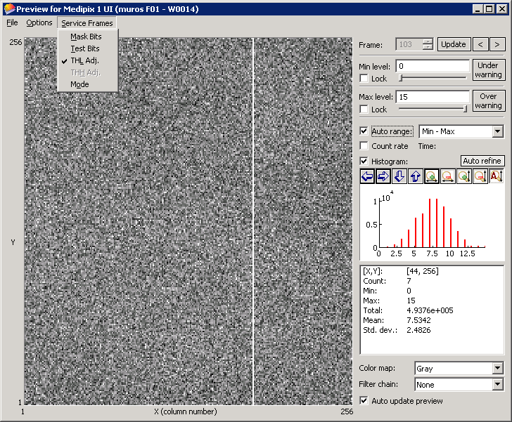
Service Frames menu contains "special frames" that represents
currently set pixels configurations. If you want to return to "normal" frame
just uncheck currently selected service frame.
- Mask Bits - mask bits (0 masked, 1 unmasked)
- Test Bits - test bits (0 enabled, 1 disabled)
- THL Adj. - THL adj. bits (0 - 7 for Medipix, 0 - 15 for Timepix)
- THH Adj. - THL adj. bits (0 - 7 for Medipix, disabled for Timepix)
- Mode - Timepix only (0 - Medipix mode, 1 - Time over threshold, 2 - Timepix 1-hit, 3 - Timepix)
Zooming in preview:
You can easily zoom in by holding left-mouse button and dragging mouse to create
selection rectangle. After releasing mouse button image view will zoom to selected
area. If you want to return to original state you can just double click with left
mouse button on the image.
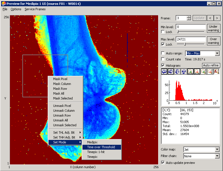
Context menu:
If you right click on the image the context menu will appear. It contains following items:
- Mask/Unmask Pixel - masks/unmasks pixel on which clicked occurred
- Mask/Unmask Column - masks/unmasks pixels in row where clicked occurred
- Mask/Unmask Row - masks/unmasks pixels in column where clicked occurred
- Mask/Unmask All - masks/unmasks all pixels
- Mask/Unmask Selected - masks/unmasks selected region (region is selected by the same way as zooming region but with holding down Ctrl key)
- Set THL Adj. Bit - sets THL to selected value for pixel or selected regions of pixels
- Set THH Adj. Bit - sets THH to selected value for pixel or selected regions of pixels (disabled for Timepix)
- Set Mode - sets operation mode to selected one for pixel or selected regions of pixels (Timepix only)
If you just click on just one pixel you can see currently selected THL/THH/Mode - there
is check mark for currently set value.
Threshold equalization
Threshold equalization is a procedure which exploits 3-bits (4-bits Timepix) THL/THH
adjustment to make overall threshold as homogenous as possible. It finds distribution
of thresholds for each adjustment value and selects for each pixel such adjustment
that its threshold is as near as possible to average of means of threshold distributions.
THL equalization - THL is scanned from above noise to the direction
of noise (real direction depends on Mpx type/polarity). If certain condition (number
of counts) is reached for a THL value then the value is added to THL distribution.
The condition for THL selection depends on eq. type:
- Use source - if selected "Count" is reached for certain pixel in specified "Time" (Acq.) "Count" and "Time" should be set according to source activity.
- Use noise edge - if selected "Count" (usually 1 or small number) is reached while coming to noise.
- Use noise center (centroid) - whole noise is scanned and the centroid of noise is considered as THL. This should not be used for original Mpx 2.1 because there is not overflow bit working.
- Use noise center (cross) - whole noise is scanned and the noise center is found as middle between values when THL enters noise and THL leaves noise. Criteria for entering and leaving is crossing selected "Count" value. This works for also Mpx 2.1.
- Use test pulses - if half of test pulses count is reached.
THH equalization - THL should be equalized and set above noise.
THH is scanned from above the noise to the direction of noise (it is used the
transition from window mode to single mode). If certain condition (number of counts)
is reached for a THH value then the value is added to THL distribution. The condition
for THH selection depends on eq. type:
- Use source - if "Counts" event is reached
- Use test pulses - If number of events reaches half of pulses sent
- Use noise - In this case THL in the middle of noise (THL is equalized, so all pixels should count). If THH is crossing THL and window has zero width the pixel should count "nothing". This condition is used. This does not work very nice because chip does not behaves exactly as expected when one is in the middle of noise with THL.
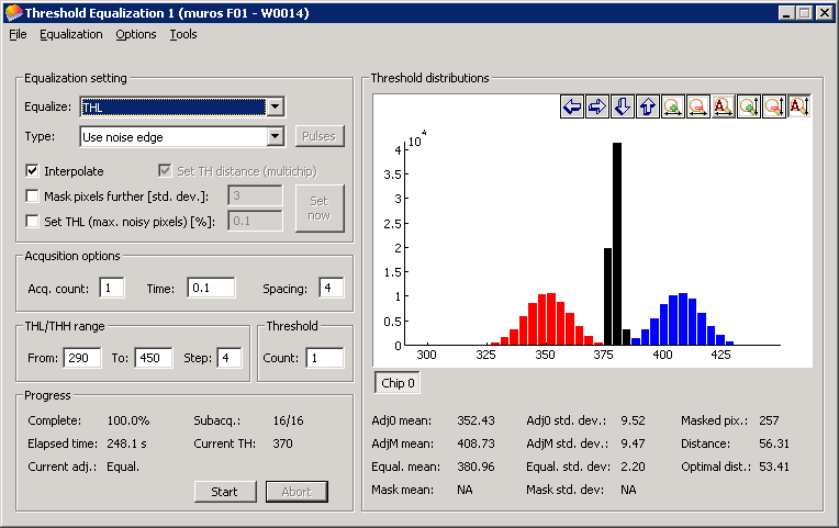
Equalization setting:
- Equalize - THL equalizes low threshold, THH high threshold
- Type - equalization type
- Pulses - if it is selected equalization type which use test pulses, click on this button to set test pulser parameters
- Interpolate - if checked the scan is performed just for adjustment value 0 and 7 and assuming linear dependency on adjustment value the adjustment bit value is interpolated
- Set TH distance - sets linear dependency between THL/THH of different chips
- Mask pixels further [std. dev.] - if checked all pixels which are further than specified value (in terms of standard deviation of threshold distribution) from mean threshold are masked
- Set THL (max. noisy pixels)[%] - if checked THL value is set to such level that the number of pixels which are in noise is less than specified value (in %)
- Set now button - Apply settings for "Mask pixels...", "Set THL..." and "Set TH distance..." (if they are checked)
Acquisition options:
- Acq. count - number of acquisition (for integral acquisition), if > 1 the criteria is usually (Acq.count*criteria), e.g. if "Threshold Count"=1 and "Acq. count"=2 and we equalize THL using noise edge the condition for THL will be "count >= 2"
- Time - time of single acquisition
- Spacing - influence how many pixels is active during single acquisition. Because of coupling effects it is necessary to have neighboring pixels masked. If spacing is 1 all pixels are active (acquisition has just 1 "subacquisition), if spacing is 2 every second pixel in each direction is active (acquisition has 4 subacquisition), if spacing is 3 every third pixel in each direction is active (there is 9 subacquisition). The reasonable compromise between speed and quality of equalization is spacing 4.
THL/THH range - set "From", "
To" and "Step". You do not need
to care if "From" should be bigger than "To
" - equalization procedure will select it properly according to Medipix
type and polarity which is selected.
Threshold Count - defines the value (for equalization with
noise/source) which has to be reached to consider the current value of THL/THH
as threshold.
Progress:
- Complete - progress of equalization (%)
- Elapsed time - elapsed time of running equalization
- Current adj. - current value of adjustment bits (0 - 7 (15 for Timepix), "Equal" for equalized scan)
- Subacq. - current subacquisition/total number of subacquisition
- Current TH - current value of threshold DAC
Results for selected chip (chip is selected by clicking on
button Chip 0, ...)
- Adj0 mean - mean of distribution of thresholds when th. adj. is 0
- AdjM mean - mean of distribution of thresholds when th. adj. is max. (i.e. 7 for Medipix, 15 for Timepix)
- Adj0 std. dev. - standard deviation of distribution when th. adj. is 0
- AdjM std. dev. - standard deviation of distribution when th. adj. is max. (i.e. 7 for Medipix, 15 for Timepix)
- Equal. mean - mean of distribution of thresholds after equalization
- Equal. std. dev.- standard deviation of distribution after equalization
- Mask mean - mean of distribution of eq. thresholds after masking according to "Mask pixels further [std. dev.]"
- Mask std. dev.- standard deviation of eq. thresholds after masking according to "Mask pixels further [std. dev.]"
- Masked pix. - Number of masked pixels, if th. eq. is started the mask bits ARE NOT cleared. If "Mask pixels further..." is unchecked the equalization procedure mask only pixels which are really bad - the distance of their threshold from mean is bigger than 6 std. dev. These masked pixels are no longer used. If mask bit is not functional in certain pixel (it counts even if it is masked) it is ignored as well. If "Mask pixels further..." is checked procedure masks all pixels which have threshold further than selected distance (in terms of std. dev.)
- Distance - computed distance of means of distribution with adjustment bits set to 0 and Max.
- Optimal distance - the distance at which the distributions (Adj0 and AdjM) overlap by 1/(AdjM+1). With assumption that we consider only pixels which are in +- 3*std. dev.: "optim. distance" is AdjM/(AdjM+1)*(3*StdDev0+3*StdDevM), where StdDev0 is standard deviation of distribution when no TH adjustment bits are set and StdDevM is when all bits are set
Distribution plot - each color corresponds to distribution when certain
th. adjustment is set (e.g. if interpolation is enabled red is for adj=0, blue for adj=Max
and black for equalized adj. bits.).
Structure of menu
- File
- Save ASCII THL adj. - saves THL adj. bits mask in ASCII format
- Save ASCII THH adj. - saves THH adj. bits mask in ASCII format
- Save Binary Pixels Cfg. - saves whole pix. cfg. to binary file
- Save Distributions - saves distribution to ASCII file
- Exit - exits plugin
- Equalization
- Start - starts equalization
- Abort - aborts equalization
- Options
- Mask Digitally Bad - if checked the digital test is performed before equalization and bad pixels are masked
- Set Th Coarse Bits - if checked the THL/THH coarse bits are set automatically according to THL/THH eq.
- Balance THL via FBK - if checked THL is balanced via FBK (to have the same threshold for same THL value for all chips)
- Equalize Chips Separately - an option mainly for MXR quads connected via MUROS. There is a power drop on SCSI cable when all chips are in noise. Therefore you can enable separate equalization of individual chips.
- Tools
- Balance THL via FBK - command for balancing THL via FBK (to do it without equalization)
DACs Scan
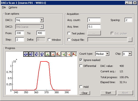
This plugin allows to see response of detector while scanning over a selected
range of any Medipix DAC or selected "window" of any two DACs. It
is useful e.g. for spectroscopic measurement with Medipix2 (with selected
THL-THH window) or for quick scan of THL/THH before equalization (to find
proper range for THL/THH).
Scan options:
- DAC1 - DAC which will be scanned in single mode, "reference" DAC for "window" scan mode (this DAC will go through selected range)
- DAC2 - second DAC for "window" scan mode; it can be selected if Window is checked; this DAC goes through range (From+Delta) to (To+Delta)
- From - To, Step - defines the range for scanning - it scans with DAC value From, From+Step, From+2*Step, ...until its <= To
- Window - if checked the "window" mode is active
- Delta - defines the width of window (the difference between DAC1 and DAC2)
Acquisition:
- Acq. count - number of acquisition to perform
- Acq. time - time of each acquisition
- Spacing - influence how many pixels is active during single acquisition. Because of coupling effects it is necessary to have neighboring pixels masked. If spacing is 1 all pixels are active (acquisition has just 1 "subacquisition), if spacing is 2 every second pixel in each direction is active (acquisition has 4 subacquisition), if spacing is 3 every third pixel in each direction is active (there is 9 subacquisition).
- Test pulses - if checked test pulses will be sent to chip, parameters can be set via "..." button
- Output file - if checked you can specify output "basic" file name for acquisition (you can browse file names with "..." button). Each acquisition taken will be written to single ASCII file. The name of file is derived in following way: if you specify as "base filename" e.g. "temp.txt" the names of files will have form "pok_DACNAME_DACVALUE_ACQNUMBER.txt" (e.g. "pok_THL_150_0.txt).
Plot:
- Count type - you can choose from Median (median count from each acquisition), Mean (mean value from each acquisition) , Total (sum of counts over all pixels)
- Chip - chip selection (all chips are scanned, selected chip's results are shown)
- Ignore masked - if checked the masked pixels are ignored from computation of Median/Mean/Total
- Differential - if a_1, a_2, ..., a_n are scanned values, the values in graph are 0, a_2-a_1, a_n-a_(n-1)
- Hold - holds the previous scan (in graph and results for save)
- Clear - clear graph and results for save
Progress:
- DAC value - current DAC value
- Current Acq. - current acquisition number
- Total progress - total progress in %
- Elapsed time - time from start of scan
Structure of menu
- File
- Save Scan - saves scans (values depends on selected Count type while saving - it saved the same scan which is shown in plot). Each line contains one scan. If Options->Save DAC Values is checked 2 lines are saved for each scan, first with DAC values, second with scan.
- Exit - closes window
- Options
- Save DAC Values - if checked 2 lines are saved for each scan, first with DAC values, second with scan.
DACs Dependency Scan
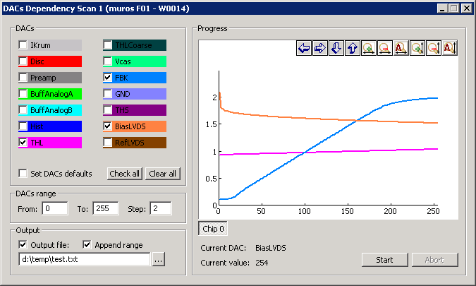
This scan shows the dependency of sensed values on digital codes of Medipix DACs.
Check the DACs which you want to scan (you can check/uncheck all with buttons
Check all and Clear all ), select the range
and step in From, To, Step
edit boxes and click on Start button. If Set DACs
defaults is checked the DACs will be set to default middle value
(128 for most) for duration of scan. Each DACs which was selected will have
its curve in graph. The curve has same color as background of the corresponding
check box. If you want output to file check Output file and
specify (or browse with "..." button) filename before
starting the scan. If you check Append range the scan range
will be appended to file name, e.g. if you specify "scan.txt", the
name of file will be "scan_From-To_step
Step.txt" (e.g. "scan_0-255_step10.txt"). The
file contains column of values for each scanned DAC, on the first line there
are DAC names as heading.
DAC Control Panel
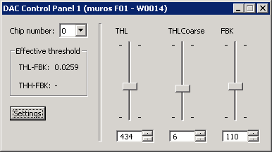
DAC Control Panel allows to instant change DACs values during series of acquisition.
If the change is not possible do immediately (e.g. acquisition is running) the
operation is postponed. If device has several chips you can select chip with
Chip number combo box. The Effective threshold
displays the difference of sensed values THL/THH and FBK. If you
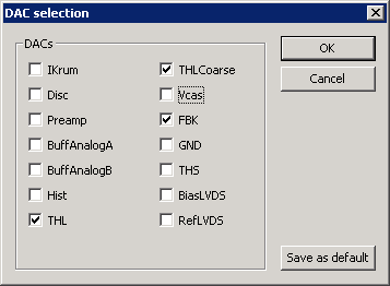
click Settings button the dialog will appear. You can check
the DACs which you want to control via DAC panel. You can use Save as
default button to save current DACs selection as default - if new chip
is connected and there is no DAC Control Panel *.ini file for this device this
default configuration will be used.
This plugin is especially useful if you need find noise level of some chips (with
certain settings) - just run few hundreds of short acquisition (e.g. 0.1 s) and
control THL slider with mouse wheel or arrow keys. You can also observe what other
plugin (e.g. Threshold equalization) does with DACs - each DAC change is immediately
visible on DAC panel.
Frame Browser
Frame Browser is plugin for easy managing of measured data (frames). It allows to
browse currently measured frames, display informations about their attributes,
loading frames from files, saving frames to files, browse directories on disks
and displaying any frame from disk.
Frames in Pixelman
"Frame" is an object representing measured or created data in Pixelman. It
consists from data buffer (possible types: i16 (2 bytes integer), u32 (4 bytes unsig.
integer), double (8 byte floating point)) and attributes associated with frame. Each
frame has ID number which is unique during Pixelman run. Attributes are associated
data (of any type) which are added to frame by the Pixelman (e.g. by MpxCtrl layer)
or by any Pixelman plugin. E.g. frame from acquisition contains informations about
acq. and Medipix settings (like acq. mode, acq. time, Mpx ID, DACs,...). If frame is
saved 2 files are created - data file which contains frame data (as
ASCII matrix or binary stream) and description file (*.dsc) which
contains information about frame type and also frame attributes. Every frame created
is available to all plugins. Any plugin can "open" frame to ensure that
frame will not be deleted by Pixelman. Each "open" operation increase
"Reference counter", each "close" decrease it. Once "Reference
counter" reaches zero frame is deleted by Pixelman.
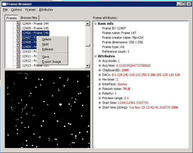
Frame browser is composed of 3 "panels": browse tree, simple preview and
attributes panel. Browse tree can display Frames in the system or
Browse files on disks (these panels can be switched by
Frames and Browse files buttons or in menu by
Options->View Frames/View Disk or by accelerator
Ctrl+1, Ctrl+2) . As you move with focus (caret)
in browse tree simple preview displays the frames immediately and frame attributes
panel is updated as well. If you want to display the frame in "Full Preview
window" you can double click with left mouse button or press "Enter"
on the selected frame.
To perform operation on several frames you can select them one by one by
Ctrl key or select interval of items by Shift
key. If whole folder is selected the operation is performed to all items in folder.
If you right click in Frames browse tree a context menu appears.
Following operations can be performed with selected frames:
- Delete - tries to delete selected frames
- Hold - holds selected frames (increase ref. counter) so it is not automatically deleted
- Release - releases selected frames (decrease ref. counter if) if they were held by Frame Browser
- Save - saves selected frames
- Export Image - save selected frames as image (PNG, BMP, TIFF, GIF, JPG, ASCII)
If browse tree is switched to Browse files the following context menu
appears after right click:
- Add - load selected frames to Pixelman
If you right click on small preview following context menu appears:
- Use Range of Current Frame - the range of currently selected frame will be used for any other frame that will be displayed later
- Use Auto Range - the range will be from minimum to maximum (in frame)
- Use Saved Range - tries to use saved Preview Range (as attribute) if exists
- Set Range... - shows dialog for specifying the range manually
Structure of menu:
- File
- Load Frames - Open multi-selection file dialog, select files you want to load
- Load Directory - Directory selection dialog - loads all frames from selected directory
- Exit - Closes window
- Options
- View Frames - switch browse tree to Frames in Pixelman
- View Disk - switch browse tree file system
- Frames
- Hold All - Frame browser opens (holds) all existing frames (increase ref. counter)
- Release All - Frame browser releases any frames it holds
- Hold New - Frame browser will hold any new frame which will be created
- Auto Update Preview - if frame is changed small preview will be immediately updated
- Attributes
- Auto Update - if some attribute is changed attribute panel is immediately updated
Filter Chain Editor
Filter Chain Editor is plugin for creating "Chain of filters". Filter
is "special" function (that can be registered by any plugin) which has
only one (beside userData par) parameter which is ID of frame. Filter will perform
some work/computation and can (but it need not) change the frame. Such operations
on frame can be chained to create one "processing pipeline" without need
to maintain it (it is maintained by Pixelman) and any plugins can used it.
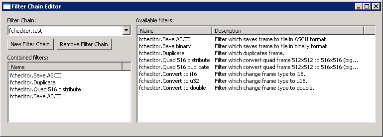
Filter Chain combo-box contains all available filter chains (their
names are classified by plugin name which created it). To create new filter chain or
remove currently selected press New Filter Chain or Remove
Filter Chain respectively. If filter chain is selected in Filter
Chain combo-box the filters which are in chain are displayed in
Contained filters list. Available filters list
contains all filters registered in Pixelman. Use drag&drop from Available
filters to Contained filters to add new filter to currently
selected filter chain. If you want to change an order of filters use drag&drop
too. Use "Delete" key to remove selected filter from current filter chain.
Example: Current "test" filter chain in the picture contains several
filter: "Save ASCII", "Duplicate", "Quad 516 distribute",
"Save ASCII". The filter chain will work in the following way: Once the filter
chain is invoked (by any plugin, e.g. by selecting in Preview window) the filters are
called one by one. First "Save ASCII" saves the input frame to file (to
"files" subdirectory in Pixelman dir), then "Duplicate" is called
which creates new frame which is duplication the input frame (to preserve original
data), then "Quad 516 distribute" filter is called which change input frame
(if it is frame from quad) from 512x512 to 516x516 to compensate for bigger pixel
(counts in bigger pixel are distributed to small ones). Then "Save ASCII"
is called again to store this recomputed 516x516 image to file.
Coincidence Control
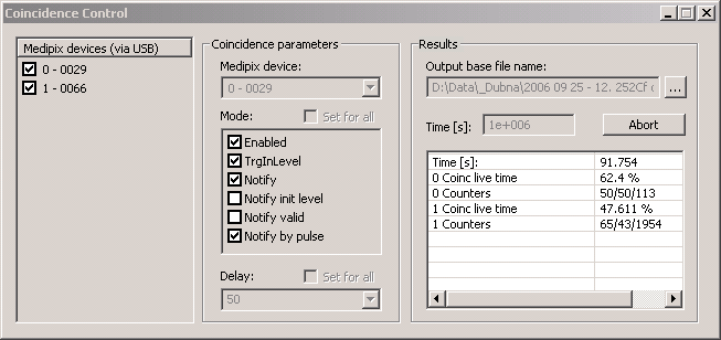
Coincidence Control plugin is simple plugin for easy setting up several Medipix devices
(connected via USB interface) to a coincidence system.
Left list contains all devices which are currently connected via USB. If you check the device
it will be added to Medipix device combo box. For each "active"
(that means checked) device you can set coincidence parameters (Mode and
Delay). You just select the device in combo box and check configuration
bits of Mode and selects Delay. If you want to set
Mode or Delay for all devices at once check corresponding
Set for all checkbox.
If Output base file name remains empty measured frames are stored
in memory otherwise they will be saved to files in ASCII format. File names are
composed of selected Output base file name, device ID and index
of frame. E.g. if Output base file name will be
"c:\temp\data.txt" and you will have two devices (with device ID 0 and 1)
connected to coincidence system data from first device will be written to files
"c:\temp\data_0_000001.txt", "c:\temp\data_0_000002.txt", "
c:\temp\data_0_000003.txt", ... and data from second one will be written
to "c:\temp\data_1_000002.txt", "c:\temp\data_1_000003.txt", ...
Time controls how long the system will measure. If
Time is set to zero the measurement will run until
Abort is pressed. Result list contains:
- Time [s] - time of measurement
- Coinc live time (for each device) - total coincidence live time (%)
- Counters (for each device) - number of triggers/valid coincidence/invalid coincidence


