

Since the FTDI driver version 2.02.04 is Microsoft WHQL certified the installation becomes very simple. Just download and run driver executable once. From then, every connected USB interface (or any other FTDI based device like Stepper motor control unit) will be recognized and installed automatically.
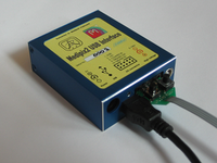 During firmware download
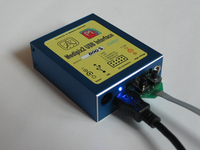 Before firmware download
The new version of the firmware can be downloaded using special serial cable via this utility. Connect the interface to the computer by USB cable (in this case it is used only as power supply) and by the serial cable. The blue control LED should be on. Note that you have to install the device drivers first!
While holding down the "Upload" button press and relase the "Reset" button.
This sets the interface in the serial download mode. The LED diode should be off so you can check if you press the buttons in correct order.
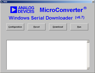 Windows Serial Downloader
Now you can start the downloading utility "wsd.exe". Screen shot of the WSD (Windows Serial Downloader) utility is shown at the left hand side of the page.
Before you start to download the new firmware you have to open the configuration window and set the crystal frequency to 20MHz. Other fields can remain at deafult values.
Now press the "Download" button, select the appropriate .HEX file and click on "Open" to download the file. For the newest version of the firmware check the download page.
During file downloading a progress bar will appear indicating how much of the file has been downloaded. To run successfully downloaded file click the "Run" button or press the "Reset" button on the serial cable. The LED should switch on indicating that program is running.
Microcontroller used in the USB interface allows to modify some parts of the program code by code itself. This feature is used to overcome the necessity od the serial cable to download new firmware. Before you will be able to use this type of firmware update you have to download special code (Bootloader) which will manage the USB downloading procedure. Find the newest version of the code on the download page.
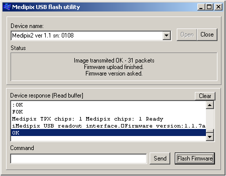 Medipix USB Flash utility
Use the same procedure described in the section Firmware downloading via serial line to download the Bootloader code. To ensure that the code will be starting from the specified adress check the "Bootload Option" in the configuration window of the serial downloader. Note that after succesfull downloading of the Bootloader code the control LED remains off.
Now you can run Medipix USB Flash utility. Connected USB interface is recognized and opened automatically. In case of multiple connected devices select one from the list and press "Open" button. Now press "Flash Firmware" button and browse the appropriate .HEX file. Note that reflashing the firmware from the Medipix USB Flash utility is supported from the firmware ver 1.1.7.
You can use the "Command" line to send specified commands to the interface - ie. command "i" returns an information string about currently running firmware, etc.
A simple software for host PC with Windows-based operating system was developed to test the functionality of the interface. Following picture shows the printscreen of the software (note that it may be slightly different against the newest version). This software is meant mainly for testing and debugging of the firmware versions. For measurement use the Pixelman package.
After start the software automatically find connected USB interfaces and recognize amount of Medipix2 chips (single, quad) - if connected. If the interface with Medipix2 chipboard is connected properly the ADC monitor is started (left side of the window) and the Medipix2 internal DACs are set to default values. You can set the high voltage in combo box at bottom right corner and you will see the change immediatelly on ADC monitor curves.
To start the basic measurement you have to reset the Medipix2 mask bits by clicking "Res. Mask" button. Than you can set the Medipix2 DACs (if you don't want to use default values) and open the shutter by clicking "Open" button in "Basic commnads" box. When you, after some time, press the "Close" button the shutter will be closed and measured data will be read-out.
To use the back-side pulse processing feature of the interface version 1.1 you need the special spectrometric plug-in PCB module (USB interface version 1.22 already integrates this module on the PCB). To open the box relase four screws and move out the front side of the box (Medipix2 chipboard side).
Before you can place the module into two 12-pin sockets you have to remove the jumper in the high voltage circuit behind the LEMO connector. Now you can plug the module into the sockets. After the module assembly put the interface back to the box and secure it using four screws
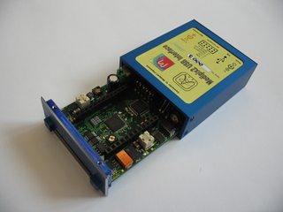 Opening the USB interface
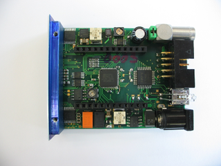 Removing jumper
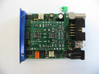 Assembling the module
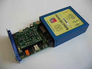 Closing the USB interface
All signal IO levels are standard 5V TTL/CMOS logic. ADC input voltage range and DAC output voltage range is from 0 to 2.5V (12-bit precision).
|
General purpose I/O connector pinout:
|
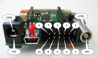 General purpose IO connector
|
|
|
Internal digital holder pinout:
|
Internal analog holder pinout:
|
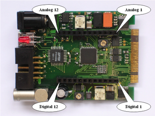 Internal plug-in headers
|